One way to think of a camera is a device that projects a 3D world in a 2D space. Humans are capable of looking at these 2D images and intuitively inferring the 3D world. For example, the relative distances, size movements, and spatial relationships of objects in the images. However, computers do not have this inherent ability.
What is camera calibration?
Camera calibration is the process of identifying the geometric characteristics of 2D images captured in 3D space. This allows image processing systems to make inferences about the scenes in these images for applications where metric information is needed. For example, in different forms of image analysis, such as 3D reconstruction, object tracking, augmented reality, etc.
To do this, a camera calibration system needs to understand the camera’s properties and have the intelligence to process and understand the context of a scene and the objects within it. This is especially true for distorted images.
The first step is to estimate the parameters of the camera (lens and image sensor). Not to mention “world” parameters such as the axis, focal length, and orientation in terms of rotation and translation vector. From there, the system can effectively map the relationships of a scene from 2D image coordinates to points in 3D space.
This has different uses:
- Correcting lens distortion
- Measuring the size and distances of objects
- Determining the location and orientation of the camera within a scene
- Building 3D models of objects captured in 2D camera motion
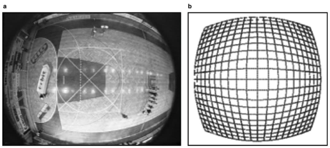
Lens distortion can be radial or tangential. Radial distortion makes straight lines appear curved; think of fisheye cameras. On the other hand, tangential distortion occurs when the lens isn’t aligned parallel to the imaging plane. Radial distortion makes the image appear curved inward or outward, while tangential distortion mostly impacts perspective.
Camera calibration has important applications in a wide variety of fields, including robotics, navigation, 3D scene reconstruction, and monitoring.
How does camera calibration work?
Two terms often used interchangeably in this context are geometric camera calibration and camera resectioning. Researchers use these techniques to estimate the parameters of a lens or image sensor.
Specifically, geometric camera calibration is the process of determining the vital characteristics of a camera. In turn, these characteristics can be divided into both intrinsic and extrinsic properties.
Intrinsic/internal properties are properties that are built into the design and specifications of the camera:
- Focal length
- Principal point
- Lens distortion
On the other hand, extrinsic/external properties involve how the camera relates to the scene in physical space:
- Position
- Orientation
Camera resectioning overlaps with geometric camera calibration to some extent, but with a slightly different nuance. It involves determining the optical center of a camera and how that relates to a specific scene or image points in 3D space. It’s a component of geometric camera calibration that primarily encompasses determining the external properties of the camera.
How to do camera calibration using a calibration pattern
Often, when developing AI models, we use existing annotated datasets to train them and test their performance. Researchers use a similar concept called a calibration pattern when it comes to camera calibration. This gives cameras equipped with computer vision a robust, baseline pattern from which to infer properties of the camera itself that may cause any distortion or changes in perspective.
By applying what it learns against the calibration pattern, it can use those properties to make predictions in more complex scenes.
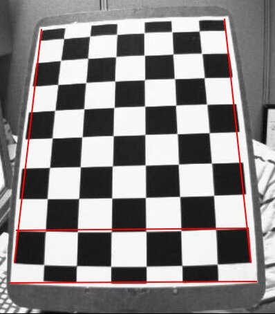
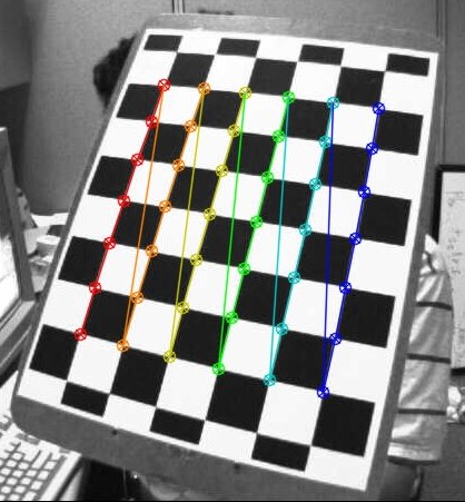
Lens distortion will be more intense on squares at the corner points of a checkerboard than in the center. By measuring the differences in distortion across the pattern, the system can make many inferences about the camera’s intrinsic properties.
The same applies to the external properties. The squares in a head-on image of the checkerboard will appear different from those taken at an angle. They will also appear to be different sizes, depending on the distance of the camera to the pattern.
It’s also important to measure these key parameters:
- The size (length and width) of the calibration pattern or calibration object
- The distance between the camera and the calibration pattern
- The orientation of the camera to the calibration pattern
- The size (in pixels) of the image of the calibration pattern/object captured by the camera
For proper calibration, it’s best to start with the camera aligned to the center of the calibration pattern with a perpendicular angle.
With this, multiple images of a calibration pattern with the camera in different poses can be taken. By collating the data, the camera parameters can be solved. Once the camera parameters are known, the findings can be applied to interpret more complex scenes.
To evaluate the accuracy of the estimated parameters, you can:
- Plot the relative locations of the camera to the calibration pattern when taking test images
- Calculate the severity of re-projection errors (how far off the camera’s estimated projections of 3D points are)
- Calculate the severity of the parameter estimation errors (errors in estimating the camera’s intrinsic and extrinsic properties)
Camera calibration matrix
At the heart of solving the camera calibration method lies the camera calibration matrix. It mathematically represents the projection relationship of 2D and 3D object points in the image with the properties of the camera. The following matrix typically represents it:
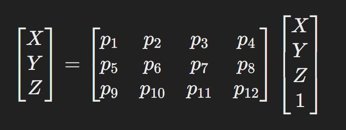
In this matrix:
- The X, Y, Z to the left represent the 2D-pixel coordinates of a point projected in image space
- The X, Y, Z, and 1 represent the homogeneous coordinates of a point in the 3D world coordinate system
- The 4×3 grid is called the “camera matrix” or “projection matrix.” It represents the intrinsic and extrinsic properties of the camera.
In the beginning, some of the metrics in the 4×3 projection matrix will be unknown. Other metrics, like the distance and angle of the camera, are under the control of the experimenter. From this point, the process basically involves taking images from different distances and angles, using the known variables to solve for the unknown variables mathematically.
Solving these equations involves various techniques, such as using linear equations or non-linear optimization methods like the Levenberg-Marquardt Algorithm.
Camera calibration models
Using various models as edge cases is useful for improved generalization and overall performance in camera calibration. You may already be familiar with the concepts of a pinhole and fisheye camera. They are considered almost complete opposites, with a pinhole camera having no lens and thus no degree of distortion. On the other hand, a fisheye camera has a thick or highly curved lens that results in intense distortion.
For example, the MATLAB Computer Vision Toolbox™ provides calibration algorithms for both models, with the one for fish eye cameras supporting a Field of View (FOV) of up to 195 degrees.
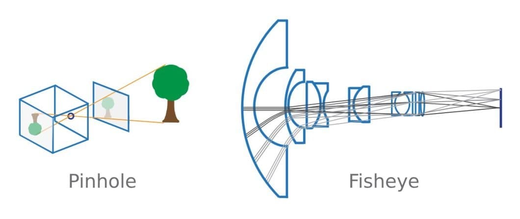
However, since they have virtually no distortion, pinhole cameras are often used to idealize the system. Computer vision models then use an algorithm to simulate radial and tangential lens distortion to better model a genuine camera. An example of this is contained in the Camera Calibration Toolbox for MATLAB by J.Y. Bouguet.
While you can model a fisheye camera starting with a pinhole camera, the opposite is not true. As a highly simplified model, the only intrinsic properties of note in a pinhole camera model are the focal length and optical center. This makes for a much easier calibration process as follows.
- The camera matrix maps the 3D scene to the image plane
- The calibration algorithm uses the intrinsic and extrinsic properties to calculate the camera matrix
- The world points are converted to camera coordinates using the extrinsic parameters
- The camera coordinates are mapped to the image plane using the intrinsic parameters
- The algorithm then uses established radial and tangential distortion coefficients to correct for it
Camera calibration guide with OpenCV
You may already be familiar with OpenCV, a comprehensive library for computer vision applications. One such application is camera calibration, powered by existing solutions such as MATLAB and ROS (Robot Operating System). Like other computer vision applications, researchers and developers favor OpenCV thanks to its accessible programming base (C/C++), versatility, and community support.
Using OpenCV, researchers can solve for both radial and tangential distortion in camera calibration scenarios. In its official documentation, OpenCV provides a complete implementation guide for camera calibration (OpenCV camera calibration). You’ll see that they use well-defined mathematical equations to represent both kinds of distortions. These models aim to calculate the distortion in both the x and y dimensions.
The end goal is to calculate the five distortion coefficients, which are also variables in the equations for radial and tangential distortion. For the camera matrix, one can take the x and y values of the focal length and optical centers as four of the nine properties of the camera.
For stereo applications, we first need to correct the observed distortions. This is where sample images of the calibration pattern step in; taken and recorded from different angles and distances. The next step is to identify specific points that we can accurately measure, such as the square corners of the chessboard.
This way, we have all the essential coordinates from real-world space. Then, comparing them to the corresponding coordinates in image space and using the algorithms provided, we can solve for the distortion coefficients. For best results, OpenCV recommends using at least 10 different test patterns.
Learn about the application of computer vision across industries and sectors:
- Image registration and its applications
- 9 applications of Computer Vision in Law and Legal Systems
- Deepfakes in the Real World: Applications and Ethics
- Computer Vision In Manufacturing: The Most Popular Applications
- Top Applications of Computer Vision in Insurance
- 16 Applications of Computer Vision in Construction